State Transition Diagram Draw Io
A state machine diagram is a beliefs that specifies the sequences of states an object goes through during its lifetime in response to events. A state machine are used to specify the behavior of objects that must respond to asynchronous stimulus or whose current behavior depends on their past. A country machines are used to model the behavior of objects, utilize cases, or even unabridged systems, specially reactive systems, which must reply to signals from actors outside the system.
In UML, state machines introduce the two new concepts in additional to traditional start chart note:
Graphically, a country is rendered every bit a rectangle with rounded corners. A transition is rendered as a solid directed line.
State
A country is a condition during the life of an object which information technology may either satisfy some condition for performing some activities, or waiting for some events to be received.
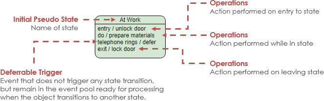
A state has five parts:
- Country Name – Name of State
- Entry – Action performed on entry to state
- Do Activity – Action performed on entry to land
- Go out State – Action performed on leaving state
- Deferrable Trigger – A list of events that are not handled in that land but, rather, are postponed and queued for handling past the object in another state
An object remains in a country for a finite corporeality of time. For example, a Heater in a home might be in whatsoever of 4 states: Idle, Cooling, Heating, Initiating and Active.
Transition
- A transition is a relationship betwixt 2 states indicating that an object in the first state will perform certain actions and enter the 2d country when a specified outcome occurs and specified atmospheric condition are satisfied.
- Transition fires means alter of state occurs. Until transition fires, the object is in the source country; after it fires, it is said to be in the target state.
- A transition has five parts:
- Source state – The state affected past the transition
- Consequence trigger – a stimulus that tin can trigger a source state to burn down on satisfying guard condition,
- Guard condition – Boolean expression that is evaluated when the transition is triggered past the reception of the event trigger,
- Activity – An executable atomic computation that may directly act on the object that owns the country machine, and indirectly on other objects that are visible to the object,
- Target state – The country that is active after the completion of the transition.

Source and Target State
Source State: The state affected by the transition; if an object is in the source country, an outgoing transition may fire when the object receives the trigger event of the transition and if the guard condition, if any, is satisfied.
Target Country: The state that is active after the completion of the transition.
Events
Event is a detached signal that happens at a point in time. It also known as a stimulus and in a kind of input to an object. Here is the characteristics of events:
- May cause a change in state
- May trigger actions – Actions tin can be internal or external
- May take associated conditions
- Signal events can exist used to communicate between country machines
Guard Status
- State transition label – Effect [Guard Status]
- Condition is a Boolean function
- Conditions are optional on state machines
- Condition is true for finite flow of fourth dimension
- When effect occurs, condition must be true for state transition to occur. If condition is fake, country transition does not occur.
Actions
Action is executed as a result of instantaneously of state transition. State transition label can be expressed as the following format
- Event / action(southward)
- Result [status] / action(south)
- Entry/go out actions
Decision Node
A Decision ode is used to represent a test condition to ensure that the control menstruation or object flow only goes down 1 path.
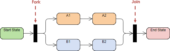
Fork node is a pseudo country used to carve up an incoming transition into ii or more transitions terminating on orthogonal target vertices. The segments outgoing from a fork vertex must not have guards or triggers and it must have exactly one incoming and at least ii outgoing transitions.
Join node is a pseudo state used to merge several transitions emanating from source vertices in dissimilar orthogonal regions. The transitions entering a join vertex cannot have guards or triggers and it must have at least 2 incoming transitions and exactly i outgoing transition.
Merge node is used to bring dorsum together different decision paths that ware created using a determination node.
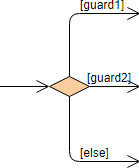
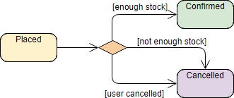
Choice is a pseudo state which, when reached, consequence in the dynamic evaluation of the guards of the triggers of its outgoing transitions. This realizes a dynamic conditional co-operative. Information technology allows splitting of transitions into multiple outgoing paths such that the decision on which path to have.
Example: Choice Node for Country Motorcar Diagram
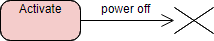
Terminate is a pseudo state indicates that the lifeline of the state automobile has ended. A terminate pseudo-state is represented past a cross.
Unlike a concluding state, a cease pseudo land implies that the land machine is ended due to the context object is terminated. In that location is no exit of whatever states nor does the country machine perform any get out actions other than the deportment associated with the transition that leads to the end state.
Composite State
A elementary state is ane which has no substructure. Composite States can exist further broken downwards into substates (either within the country or in a split up diagram). A state which has substates (nested states) is called a composite state.
- Substates may be nested to whatsoever level.
- A nested state machine may have at most one initial land and 1 final land.
- Substates are used to simplify complex flat state machines by showing that some states are only possible within a particular context (the enclosing state).

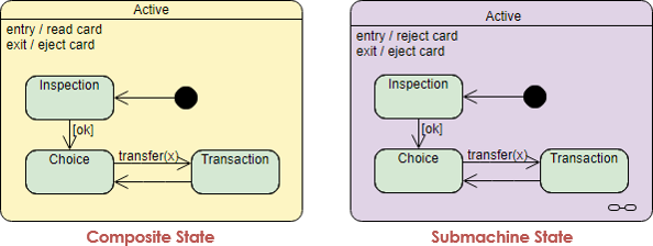
Composite Country vs Submachine Land
Besides blended state, there is another symbol called submachine country, which is semantically equivalent to a composite state.
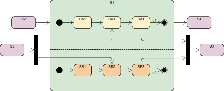
Orthogonal State
A composite state with two or more regions is called orthogonal. Dissimilar blended states, submachine states are intended to group states, so you can reuse them. Orthogonal land is divided into two or more regions separated by a dashed line:
- One state of each region is e'er active at any signal in time, i.e., concurrent substrates
- Entry: transition to the boundary of the orthogonal state activates the initial states of all regions
- Go out: last country must be reached in all regions to trigger completion effect
Notation That:
Y'all tin use parallel and synchronized node to ordinate different substates. Concurrent Substates are independent and tin can consummate at dissimilar time.
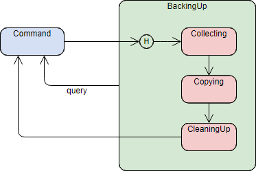
History State – Shallow / Deep
History states allow the country machine to reenter the last substate that was active prior to leaving the composite state. An example of history state usage is presented in the figure below:
A Use Instance model can be developed by following the steps beneath.
The Digital Clock State Auto diagram instance below shows the interface of a simple digital clock:
Some more Country Machine Diagram examples are provided beneath.
This instance represents ii sets of concurrent substates by using ii regions.
This example represents 2 sets of concurrent substates by using two regions.
Source: https://online.visual-paradigm.com/diagrams/tutorials/state-machine-diagram-tutorial/
0 Response to "State Transition Diagram Draw Io"
Postar um comentário